
Figure 4 is part of 3D Systems’ scalable platform for manufacturing solutions ranging from Figure 4 Jewelry, Figure 4 Standalone, Figure 4 Modular, and Figure 4 Production.
Figure 4, using Non-Contact Membrane Digital Light Technology, delivers ultra-fast additive manufacturing technology that offers the expandable capacity to meet your present and future needs with a wide range of innovative materials.
Which series is more suitable for you?
Figure 4 Jewelry is designed to address three application-specific workflows: jewelry casting patterns, master patterns for molds, and prototype/fit check models.
Figure 4 Standalone is suitable for same-day prototyping and direct digital production of tens and hundreds of parts per month.
Figure 4 Modular is expandable up to 24 print engines for automated job management and queuing, automated material delivery, and centralized post-processing.
Figure 4 Production is the choice for producing 1 million+ parts per year for a broad range of industrial, dental, and custom materials. It is customizable and automated direct 3D production solution with configurable, in-line production cells.
What are the differences in build process and post-process between Figure 4 and Stereolithography (SLA)?
The fundamental difference in build process is Figure 4 is a projection-based technology whereas SLA is a laser vector-based technology. Using Figure 4 projection-based technology, there is no time relationship between layer time and cross-sectional details. Using SLA’s vector-based technology, it uses a single point of light to cure material that travels around the system at high speed; there is a time correlation between cross-sectional area, perimeter, details, quantity and complexity.
Another difference is the frequencies where SLA is 365nm and Figure 4 is 305nm.
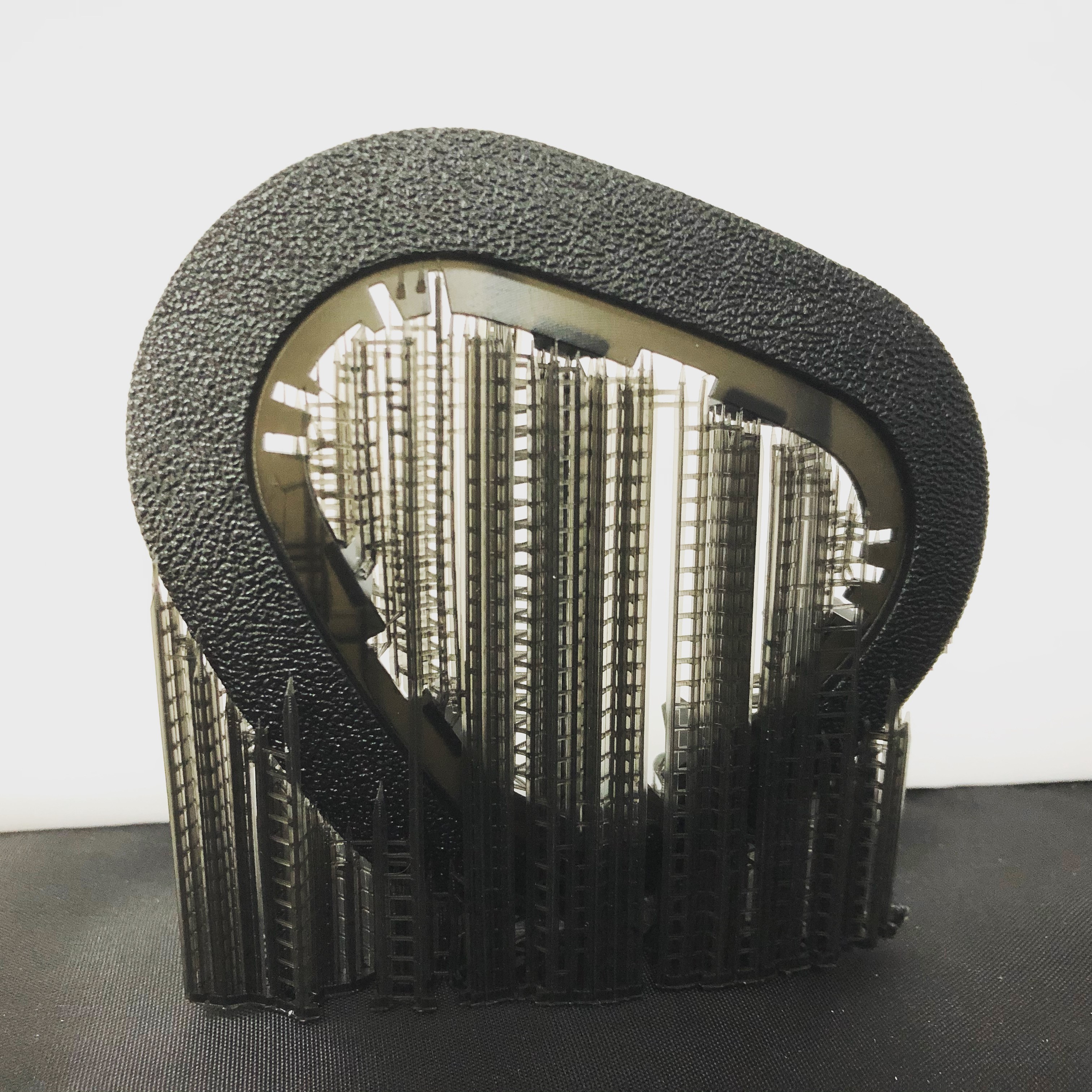
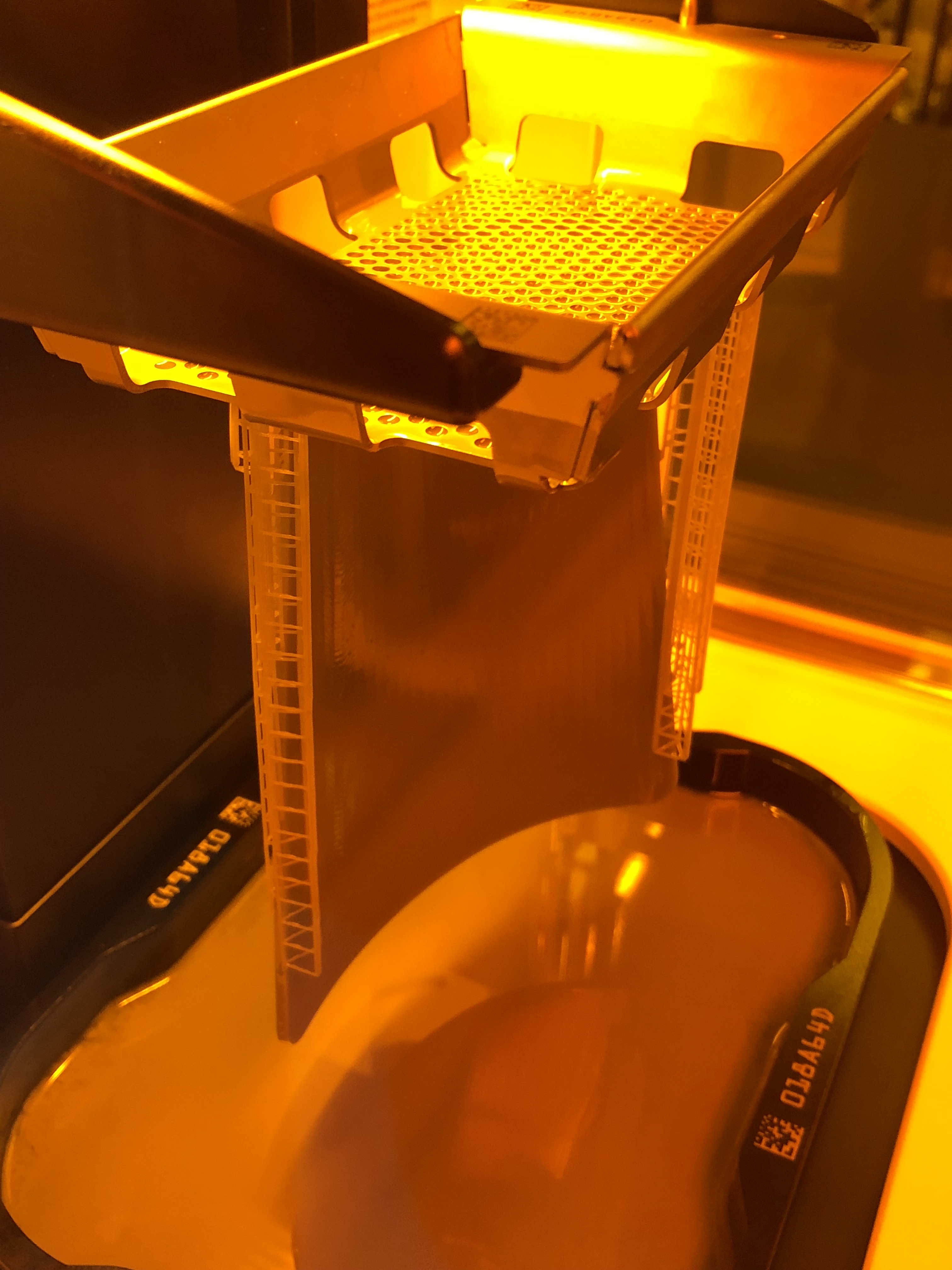 Lastly, Figure 4’s parts are built upside down and the three-dimensional object is pulled upward from a membrane. SLA’s parts are built upright, submerged in a vat of fluid.
Because Figure 4 parts are built on a non-contact membrane, there is no surface meniscus and it is possible to achieve very thin layers. With the combination of the projection process, the print speeds with Figure 4 are very high (e.g. Vertical build speed was 63mm/hr with a total build of 5 hours and 15 minutes).
What is the layer height for Figure 4?
Taking an example using Figure 4 PRO-BLK 10 production material, the standard mode layer thickness is 0.05mm. It can be adjusted based on application requirements. Some 3D Systems application samples can go all the way down to 10um layer thickness.
What is the dimensional stability between the first and last layer of parts of all stacked parts pull and stretching everything down (taking an example of a total weight of 6kg)?
The stability is very consistent as there is very little variation in the function of when and where it was built within the system.
What is the maximum build envelope for Figure 4?
The printable build volume (W x D x H) on Figure 4 Production and Figure 4 Modular systems is 124.8 x 70.2 x 436 mm (4.9 x 2.8 x 13.6 in). The printable build volume for Figure 4 Standalone and Figure 4 Jewelry is 124.8 x 70.2 x 196 mm (4.9 x 2.8 x 7.7 in).
 Is Figure 4 PRO-BLK 10 similar to ABS, or stronger?
Figure 4 PRO-BLK 10 and ABS share some similar characteristics. Figure 4 PRO-BLK 10 demonstrates very good life cycle stability that is similar to off-the-shelf, commodity-grade polyurethane.
What is the minimum wall thickness that Figure 4 PRO-BLK 10 material can print?
It depends on aspect ratio, the orientation of features, and the material. With some electronic connector applications, 3D Systems have expressed 150um vertical walls for short length; they had also worked on production-scale mass complex casting applications that routinely express 300um vertical walls over several inches.
What is the part accuracy and tolerances Figure 4 can hold?
The accuracy is dependent on the geometry, not just the size of the part but also the shape and cross-sections. As such, the accuracy capability is best evaluated in the context of a specific part example.
Credits thanks for the above answers provided by Patrick Dunne, VP, Advanced Application Engineer